Physics-
General
Easy
Question
The magnetic induction at the centre O of the current carrying bent wire shown in the following diagram is:

The correct answer is: 
Related Questions to study
Physics-
Three long straight wires A,B and C are carrying currents as shown in the figure. The resultant force on B is directed:

Three long straight wires A,B and C are carrying currents as shown in the figure. The resultant force on B is directed:

Physics-General
Physics-
An ammeter of range 5 A is to be converted into an ammeter of range 10 V. If the resistance of ammeter be 0.1  , then what resistance should be converted in series with it?
An ammeter of range 5 A is to be converted into an ammeter of range 10 V. If the resistance of ammeter be 0.1  , then what resistance should be converted in series with it?
Physics-General
Physics-
In the following figure, the value of resistor to be connected between C and D so that the resistance of the entire circuit between A and B does not change with the number of elementary sets used is

In the following figure, the value of resistor to be connected between C and D so that the resistance of the entire circuit between A and B does not change with the number of elementary sets used is

Physics-General
Physics-
Figure shows three resistor configurations R1,R2 and R3 connected to 3 V battery. If the power dissipated by the configuration R1 R2 and R3 is P1,P2 and P3, respectively, then (figure) :

Figure shows three resistor configurations R1,R2 and R3 connected to 3 V battery. If the power dissipated by the configuration R1 R2 and R3 is P1,P2 and P3, respectively, then (figure) :

Physics-General
Physics-
The three resistances of equal value are arranged in the different combinations shown in figure. Arrange them in increasing order of power dissipation :
I) 
II) 
III) 
IV) 
The three resistances of equal value are arranged in the different combinations shown in figure. Arrange them in increasing order of power dissipation :
I) 
II) 
III) 
IV) 
Physics-General
Physics-
If in the circuit, power dissipation is 150 W, then R is :

If in the circuit, power dissipation is 150 W, then R is :

Physics-General
Physics-
For maximum power dissipated in the external load of resistance R, R =

For maximum power dissipated in the external load of resistance R, R =

Physics-General
Physics-
Two cells of emf 4 V and 6 V are connected to an external load R = ¾ ohm. If = ¼ ohm the power dissipated in the load is

Two cells of emf 4 V and 6 V are connected to an external load R = ¾ ohm. If = ¼ ohm the power dissipated in the load is

Physics-General
General
The property of attracting or repelling objects on rubbing is called_____________.
The property of attracting or repelling objects on rubbing is called_____________.
GeneralGeneral
Physics-
In the given circuit, the voltmeter records 5 V. The resistance of the voltmeter (in ohms) is

In the given circuit, the voltmeter records 5 V. The resistance of the voltmeter (in ohms) is

Physics-General
Physics-
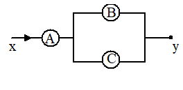
A, B and C are voltmeters of resistance R, 1.5 R and 3R respectively. When same potential difference is applied between x and y, the voltmeter readings are VA, VB and VC. Then 
A, B and C are voltmeters of resistance R, 1.5 R and 3R respectively. When same potential difference is applied between x and y, the voltmeter readings are VA, VB and VC. Then 
Physics-General
Physics-
In the figure, if the ammeter reads 5 A and voltmeter reads 50 V, then the resistance R is

In the figure, if the ammeter reads 5 A and voltmeter reads 50 V, then the resistance R is

Physics-General
Physics-
In the circuit shown, the reading of the voltmeter V is

In the circuit shown, the reading of the voltmeter V is

Physics-General
Physics-
In the circuit shown here the readings of the ammeter and voltmeter are

In the circuit shown here the readings of the ammeter and voltmeter are

Physics-General
Physics-
If an ammeter is to be used in place of a voltmeter, then we must connect ammeter with a:
If an ammeter is to be used in place of a voltmeter, then we must connect ammeter with a:
Physics-General


