

Physics-
General
Easy
Question
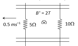
A pair of parallel conducting rails lie at right angle to a uniform magnetic field of 2.0 T as shown in the fig. Two resistors 10  and 5 are to slide without friction along the rail. The distance between the conducting rails is 0.1 m. Then

- Induced current
 directed clockwise if 10 W resistor is pulled to the right with speed 0.5 ms–1 and
  resistor is held fixed
- Induced current
 directed anti-clockwise if 10 W resistor is pulled to the right with speed 0.5 ms–1 and resistor is held fixed
- Induced current directed clockwise if 5 W resistor is pulled to the left at 0.5 ms–1 and 10 W resistor is held at rest
- Induced current directed anti-clockwise if 5 W resistor is pulled to the left at 0.5 ms–1 and 10 W resistor is held at rest
directed clockwise if 10 W resistor is pulled to the right with speed 0.5 ms–1 and resistor is held fixed
directed anti-clockwise if 10 W resistor is pulled to the right with speed 0.5 ms–1 and resistor is held fixed
directed clockwise if 5 W resistor is pulled to the left at 0.5 ms–1 and 10 W resistor is held at rest
directed anti-clockwise if 5 W resistor is pulled to the left at 0.5 ms–1 and 10 W resistor is held at rest
The correct answer is: Induced current directed anti-clockwise if 5 W resistor is pulled to the left at 0.5 ms–1 and 10 W resistor is held at rest
When resistor is pulled left at 0.5 m/sec induced emf., in the said resistor = 
Resistor  is at rest so induced emf in it
  be zero.
Now net emf.,
in the circuit 
and equivalent
resistance of the circuit
R = 15 W
Hence current 
And its direction will be anti-clockwise (according to Lenz’s law)
Related Questions to study
physics-
Two coils P and Q are placed co-axially and carry current I and I' respectively

Two coils P and Q are placed co-axially and carry current I and I' respectively
physics-General
physics-
An alternating voltage of 141.4V (rms) is applied to a vacuum diode as shown in the figure. The maximum potential difference across the condenser will be

An alternating voltage of 141.4V (rms) is applied to a vacuum diode as shown in the figure. The maximum potential difference across the condenser will be
physics-General
physics-
The diagram of a logic circuit is given below. The output F of the circuit is represented by

The diagram of a logic circuit is given below. The output F of the circuit is represented by
physics-General

physics-
The shows two NAND gates followed by a NOR gate. The system is equivalent to the following logic gate

The shows two NAND gates followed by a NOR gate. The system is equivalent to the following logic gate
physics-General
physics-
The combination of gates shown below produces

The combination of gates shown below produces
physics-General
physics-
Figure gives a system of logic gates. From the study of truth table it can be found that to produce a high output (1) at R, we must have

Figure gives a system of logic gates. From the study of truth table it can be found that to produce a high output (1) at R, we must have
physics-General

physics-
The following configuration of gate is equivalent to

The following configuration of gate is equivalent to
physics-General
physics-
For the transistor circuit shown below, if , voltage drop between emitter and base is 0.7 V then value of will be

For the transistor circuit shown below, if , voltage drop between emitter and base is 0.7 V then value of will be
physics-General
physics-
In the following circuit find and

In the following circuit find and
physics-General

physics-
In the circuit shown in figure the maximum output voltage  is
is

In the circuit shown in figure the maximum output voltage is
physics-General
physics-
Ge and Si diodes conduct at 0.3 V and 0.7 V respectively. In the following figure if Ge diode connection are reversed, the valve of V0 changes by

Ge and Si diodes conduct at 0.3 V and 0.7 V respectively. In the following figure if Ge diode connection are reversed, the valve of V0 changes by
physics-General
physics-
A diode is connected to 220 V (rms) ac in series with a capacitor as shown in figure. The voltage across the capacitor is

A diode is connected to 220 V (rms) ac in series with a capacitor as shown in figure. The voltage across the capacitor is
physics-General
physics-
In which of the following circuit is the current maximum just after the switch S is closed

In which of the following circuit is the current maximum just after the switch S is closed
physics-General
maths-
Range of function f(x) =  is given by
Range of function f(x) = is given by
maths-General
physics-
Find VAB

Find VAB
physics-General


